
Points
In SCADA systems, points are units of information read from the control devices defined in the system.
There is a relationship between each point created and an input or output register of some connected device. The point’s indication will be updated periodically according to the value of the register.
In turn, the system’s points have a graphical counterpart in the symbols that represent them. The relationship between a point and a symbol is established through its Name and its Sub-name.
When defining a Point, a Function, a Limit Set, an Alarm Group, a Text Set, and a Command Set are specified:
- The Function is used to convert the value of the register from which the point’s information is taken into its indication
- The Limit Set is used to generate the corresponding alarms when the point’s indication violates the limits established in the set
- The Alarm Group is used to categorize the alarms produced by the point, to set the text color in the alarm list, and to determine which Users should be alerted when changes generate alarms
- The Text Set is used to determine what text should be displayed on screen along with alarms for each possible indication in digital points
- The Command Set, when its use is enabled, determines the action to be carried out when the system operator attempts to execute a command through the graphical symbol
Screenshot
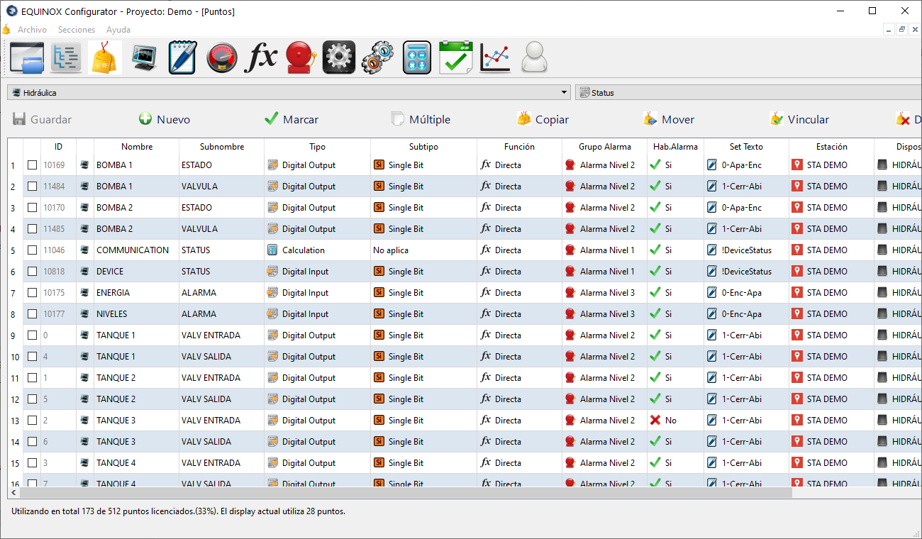
Creating points
Points are created automatically when inserting a graphical symbol into a Display, after naming it from EQUINOX Web; for more information see the display creation example
Point parameter configuration
Selecting the graphical point type
Select from the dropdown list located in the upper left the SCADA display you are going to work on.
Selecting the graphical point type
Select from the dropdown list located in the upper right the list to display on screen according to the graphical point type. The options are:
| Symbol type | Nature | Description |
|---|---|---|
| Status | Digital | Overlapping drawings, one for each possible state; the one corresponding to the point’s current state will be shown and the rest hidden |
| Measure | Analog | Numeric value related to the current value of the analog point, converted to engineering units through scaling |
| Bar | Analog | Bar whose height depends on the current value of the analog point |
| Gauge | Analog | Needle meter |
| Static | — | Does not change graphically; usually used to implement actions or links between Displays |
Description of point parameters
Name and sub-name
The Name and the Sub-name uniquely identify the point in the system and relate it to the corresponding graphical symbol.
When a value change occurs in the point, the system searches the display for symbols with the same Name and Sub-name to reflect the change in its appearance.
In general, the Name can be thought of as a general category, for example PUMP1, and the Sub-name as a particular characteristic, for example SPEED, TEMPERATURE, STATUS, etc:
Type and Subtype
Related to the data acquisition side. The possible values are:
Digital Input / Digital Output type
Input or output states with a length of up to 8 consecutive bits. Can be associated with Status type symbols.
| Subtype | Description | |
|---|---|---|
 |
Single Bit | 1 bit, which can take 2 states: 0 or 1 |
 |
Dual Bit | 2 consecutive bits, which can take 4 states: 0 to 3 |
 |
Triple Bit | 3 consecutive bits, which can take 8 states: 0 to 4 |
 |
Quad Bit | 4 consecutive bits, which can take 16 states: 0 to 15 |
 |
Penta Bit | 5 consecutive bits, which can take 32 states: 0 to 31 |
 |
Hexa Bit | 6 consecutive bits, which can take 64 states: 0 to 63 |
 |
Hepta Bit | 7 consecutive bits, which can take 128 states: 0 to 127 |
 |
Octa Bit | 8 consecutive bits, which can take 256 states: 0 to 255 |
Register Input 16 / Register Output 16 type
Input or output registers with a length of 16 bits, that is, two bytes. Can be associated with Status, Measure, Bar or Gauge type symbols.
| Subtype | Description | |
|---|---|---|
 |
8 Bits LSB | 16-bit register, low part (least significant byte) |
 |
8 Bits MSB | 16-bit register, high part (most significant byte) |
 |
16 Bits | Full 16-bit register |
 |
16+16 Bits | Two consecutive 16-bit registers (32 bits total) |
 |
Bit 0 to Bit 15 | One bit of the 16-bit register (Bit No. 0 to 15) to assign to Status type symbols |
|
Bit 0&1, 1&2, etc | Two consecutive bits of the 16-bit register (Bits 0 and 1, 1 and 2, 2 and 3, etc.) to assign to Status type symbols |
Register Input 32 / Register Output 32 type
Input or output registers with a length of 32 bits, that is, four bytes. Can be associated with Status, Measure, Bar or Gauge type symbols. 32-bit data types only apply to protocols that support objects of this length (e.g.: DNP3).
| Subtype | Description | |
|---|---|---|
 |
8 Bits B0 | 32-bit register, byte No. 0 (least significant) |
 |
8 Bits B1 | 32-bit register, byte No. 1 |
 |
8 Bits B2 | 32-bit register, byte No. 2 |
 |
8 Bits B3 | 32-bit register, byte No. 3 (most significant) |
 |
16 Bits Low | 32-bit register, low part (least significant 16 bits) |
 |
16 Bits High | 32-bit register, high part (most significant 16 bits) |
 |
32 Bits | Full 32-bit register |
 |
Bit 0 to Bit 31 | One bit of the 32-bit register (Bit No. 0 to 31) to assign to Status type symbols |
|
Bit 0&1, 1&2, etc | Two consecutive bits of the 32-bit register (Bits 0 and 1, 1 and 2, 2 and 3, etc.) to assign to Status type symbols |
Calculation type
Points of this type have two uses:
- Representing the status of a Device or communication Channel (if you enter its ID in the Status Point field of that element).
- Assigning them a Function in the Calculations section, to calculate the value of these points based on the value of other points or values taken from the database
Other definitions
| Definition | Description |
|---|---|
| Functions | Conversion of raw counts to engineering units (e.g. the register value is 996 and this is converted to 9.96V, corresponding to a voltage). Double-clicking this cell shows the list of defined Functions. Sets are created in the Conversion Sets section. Applies only to Register Input/Output type points. |
| Limit Set | Defines from which values analog points will generate alarms. Double-clicking this cell shows the list of defined Limit Sets. Sets are created in the Limit Sets section. Applies only to Register Input/Output type points. |
| Alarm Group | Assigns this point to a certain alarm group; these groups can, for example, determine critical and non-critical alarms. Double-clicking this cell shows the list of defined Alarm Groups. Groups are created in the Alarm Groups section. |
| Alarm Enable | Determines whether a state change in the point will generate an alarm or not. Digital Input/Output type points: generate an alarm on state change; Register Input/Output type points: generate an alarm when limits are exceeded. |
| Text Set | For Digital Input/Output points: assigns a text to each possible state of the point, for example 0 equals OPEN and 1 equals CLOSED. For Register Input/Output points: texts to show for each exceeded limit. |
| Station | Station from which this point will be read. |
| Device | Device assigned to the previous station (in the Element Tree section) from which this point will be read. |
| Index | Enter the index or register within the device to which this point corresponds (not counting the base address, example: for 40.005 enter 5). |
| Action | Action on clicking the Symbol: Blocked, Command (the defined telecommand will be executed) or Link (another display will be accessed) |
| Target | If Link is selected in the Action column, the target display of the Link is specified here. |
| Command Set | If Command is selected in the Action column, double-clicking this cell shows the list of defined Command Sets. Sets are created in the Command Sets section. |
Mark and Multiple buttons
These functions allow selecting points from the list according to certain criteria, in order to then apply bulk changes to all of them.
Mark
Allows you to select or deselect points based on any column of the table, according to certain criteria depending on the selected column
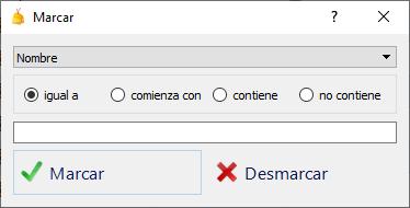
You must choose the column for which you want to select or deselect points, then set a criterion according to the following table, and finally click Mark to select or Unmark to deselect.
| Column | Selection or deselection criterion |
|---|---|
| Name | Points whose Name equals, starts with, contains, or does not contain a certain entered text |
| Sub-name | Points whose Sub-name equals, starts with, contains, or does not contain a certain entered text |
| Type | Points of a certain Type to select, according to the symbol type selected in the dropdown list |
| Subtype | Points of a certain Subtype to select, according to the symbol type selected in the dropdown list |
| Function | Points whose Function is the one selected |
| Alarm Group | Points whose Alarm Group is the one selected |
| Alarm Enable | Points that have alarm generation enabled or disabled |
| Text Set | Points whose Text Set is the one selected |
| Station | Points that belong to a certain Station |
| Device | Points that belong to a certain Device |
| Index | Points whose Index is the one entered |
| Action | Points whose Action is the one selected |
| Target | Points whose target Display is the one selected |
| Command Set | Points whose Command Set is the one selected |
This operation can be repeated as many times as desired to refine the selection of points, for example selecting all points that have alarm generation enabled (Alarm Enable: Yes), and then deselecting only those that belong to a certain Station.
Selection can also be done manually, using the checkboxes located to the left of each point.
Multiple
Allows you to perform a bulk edit on previously selected points, so as to set the same configuration for a particular column across all of them.
The possible edits for each column are as follows:
| Column | Edit |
|---|---|
| Name | Find a text and replace it with another, insert a prefix or suffix, or change the entire text to another in the Name of the selected points |
| Sub-name | Find a text and replace it with another, insert a prefix or suffix, or change the entire text to another in the Sub-name of the selected points |
| Type | Set a certain Type on the selected points |
| Subtype | Set a certain Subtype on the selected points |
| Function | Set a certain Function on the selected points |
| Alarm Group | Set a certain Type on the selected points |
| Alarm Enable | Enable or disable alarm generation on the selected points |
| Text Set | Set a certain Text Set on the selected points |
| Station | Set a certain Station on the selected points |
| Device | Set a certain Device on the selected points |
| Index | Find an Index and replace it with another, insert a prefix or suffix, or change the Index to another on the selected points |
| Action | Set a certain Action on the selected points |
| Target | Set a certain target Display on the selected points |
| Command Set | Set a certain Command Set on the selected points |
Other buttons
| Button | Description |
|---|---|
| Save | Saves the changes made |
| Copy | Copies the selected points to a given display; this operation will increase the number of points used |
| Move | Moves the selected points to a given display |
| Link | Links the selected points to a given display; using this option, there is a single point that is graphically represented on multiple displays |
| Unlink | Unlinks the selected points from the current display |
| Delete | Deletes the selected points |